2D Vehicles
One weekend in late August 1996, I wrote a 2D physics simulation which later became the basis of the vehicle system in the eventually popular game "Grand Theft Auto" aka "GTA".
It began as a little wireframe demo written in GFA BASIC on my Atari ST home computer (and was later ported to C for use in the actual game).
I have recreated* it here in JavaScript for its 30th anniversary in a slightly prettier, "remastered" form, for anyone who is interested in seeing or playing it.
Play Motion Lab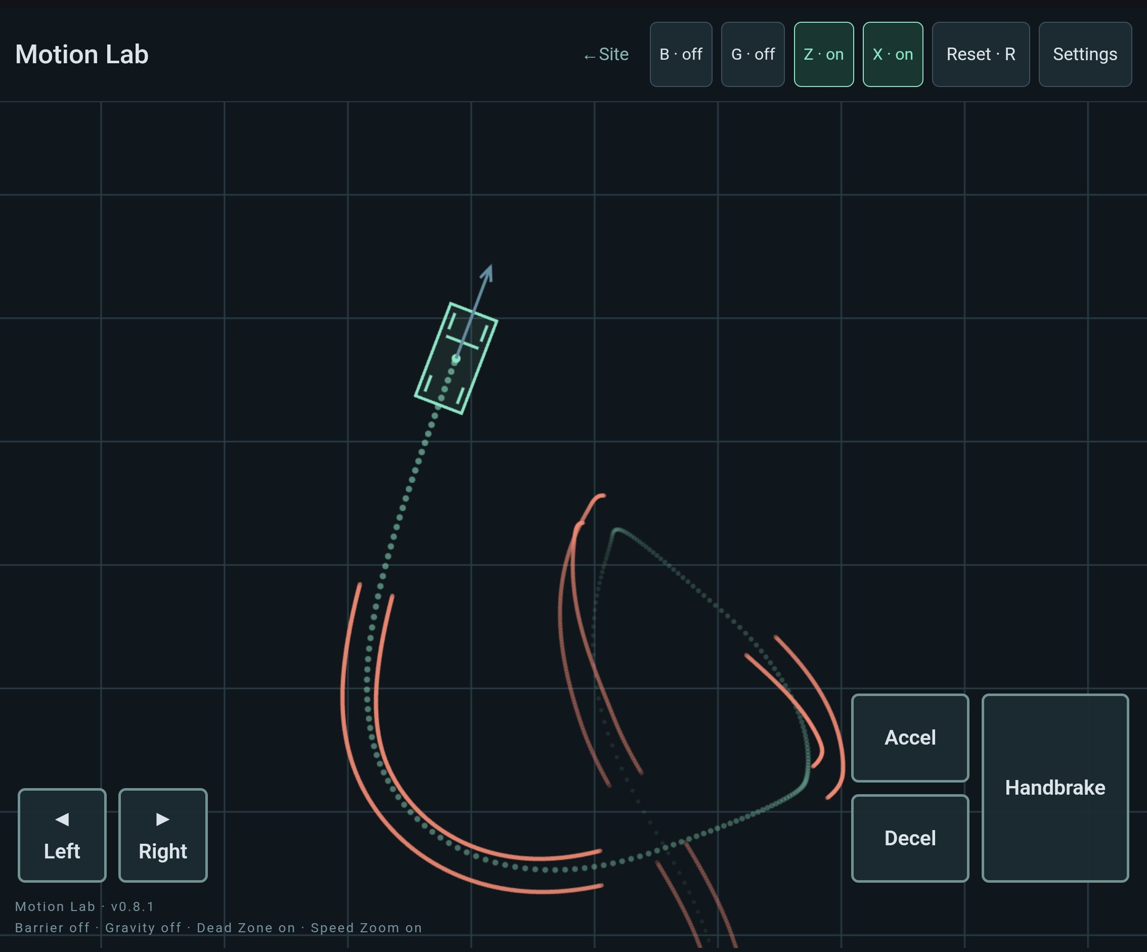
You can play the recreation above, with touch controls if you are on mobile.
In addition to the default "Car" mode (1), you can also select the technically simpler Spaceship aka "Ship" (2) and "Brick" (3) modes, either via the mode selector in Settings or by pressing the corresponding numbers on your keyboard.
Collision barriers around the sides of the playfield can be toggled by clicking or pressing "B", and "G" toggles vertical gravity (which only really makes sense in the Ship and Brick modes).
Camera controls are provided by "Z" and "X": "Z" toggles what is called the camera's "dead zone", which changes how far the vehicle can move before the camera follows it; "X" toggles a speed-related zoom feature which pulls the camera back a bit when you are going faster (just like in GTA).
*(in an entirely non-copyright and non-trademark infringing way, of course)
[VOLUNTARY DISCLAIMER: This work is wholly independent of, and in no way affiliated with, the "Grand Theft Auto" franchise and its publisher "Take-Two", or the developer entity known as "Rockstar Games". I am more than happy to make this abundantly clear. Delighted, even.]
A small idea with two layers.
The prototype combined a general-purpose 2D rigid body with a deliberately simple model of a car.
The original simulation started with something like the "Brick", and I then added some enhancements to make the "Ship" (which is deliberately reminiscent of the classic game "Thrust" from 1986), before finally adding the elements which were required to make it feel a bit more like a "Car".
At the core of the system is a simple classical 2D rigid body dynamics simulation. From what I can tell, this approach was not yet common in games at the time (with some notable exceptions), and most game vehicles were done using basic high-school ‘point physics’ (F = ma), with any rotational component being handled by various wonky "hacks". Using proper rigid-body physics (including torques) handles rotation more coherently.
On top of that core, I then added a "novel" vehicle simulation layer, based on a simple, approximate, and technically incorrect model of how tyres behave. It was basically a semi-educated guess on my part and, although I knew it wasn't really physically accurate, it nevertheless seemed to be "good enough" for my purposes at the time.
From input to motion
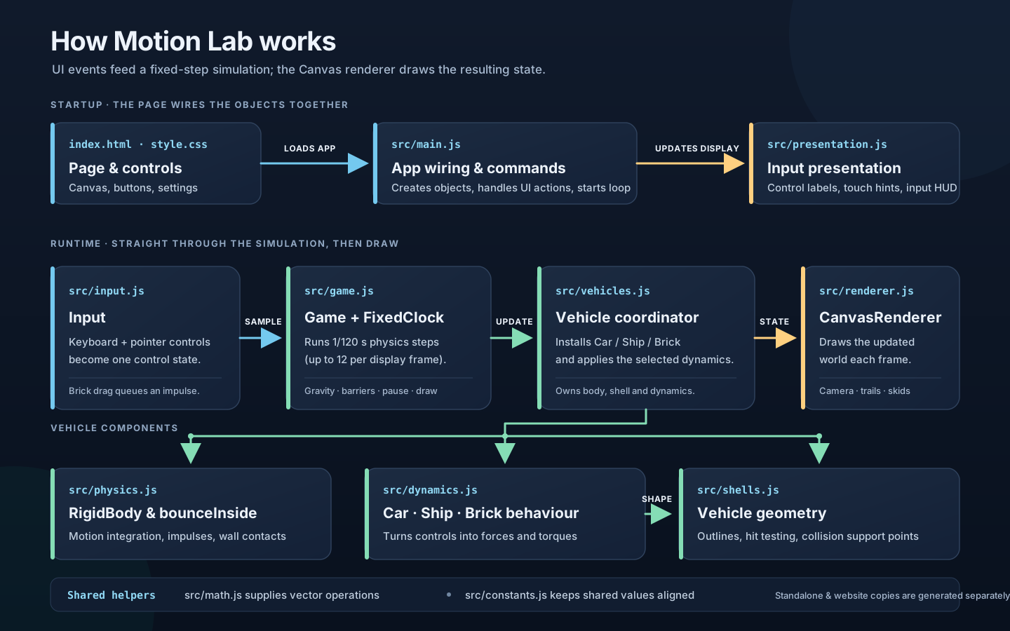
These diagrams describe the current JavaScript recreation. The browser interface supplies the controls, the simulation advances in fixed time steps, and the Canvas renderer draws the resulting state. Keeping those jobs separate makes it easier to follow where a button press becomes a force, and where that force becomes movement. Select any diagram to open it at full size.
One body, three behaviours
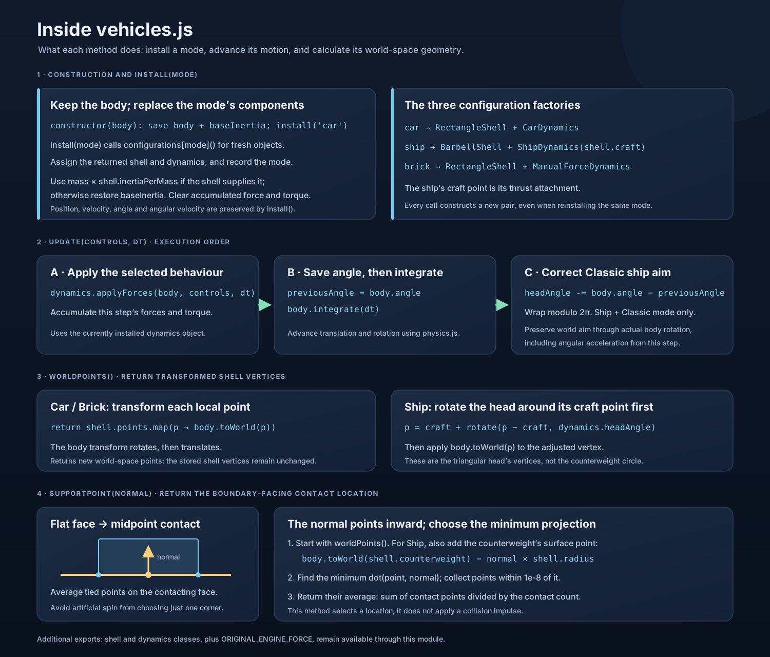
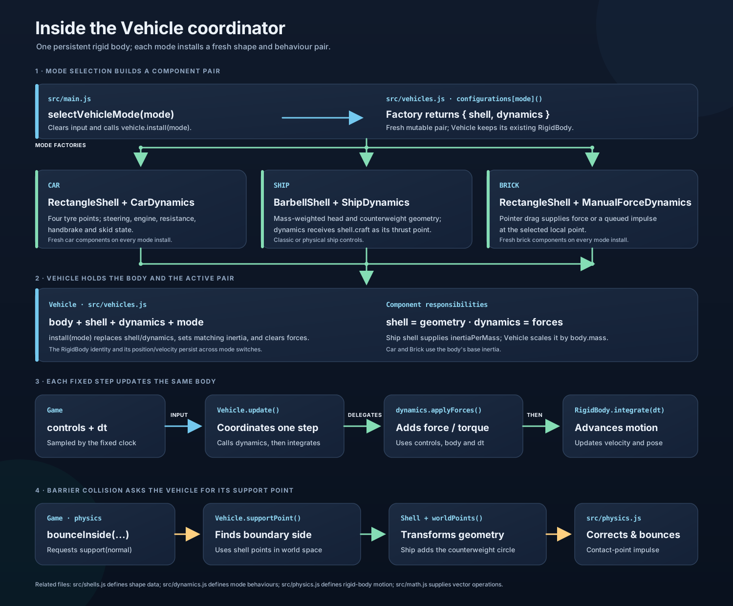
A vehicle combines a rigid body with a shell that describes its display shape and collision geometry, and a dynamics object that supplies its behaviour. The Brick accepts forces from a pointer drag; the Ship adds thrust at an attachment point; the Car adds engine force and steering, with resistance applied at four tyre positions. Switching mode replaces the shell and behaviour while preserving the body's position and motion.
Forces can move and turn the body
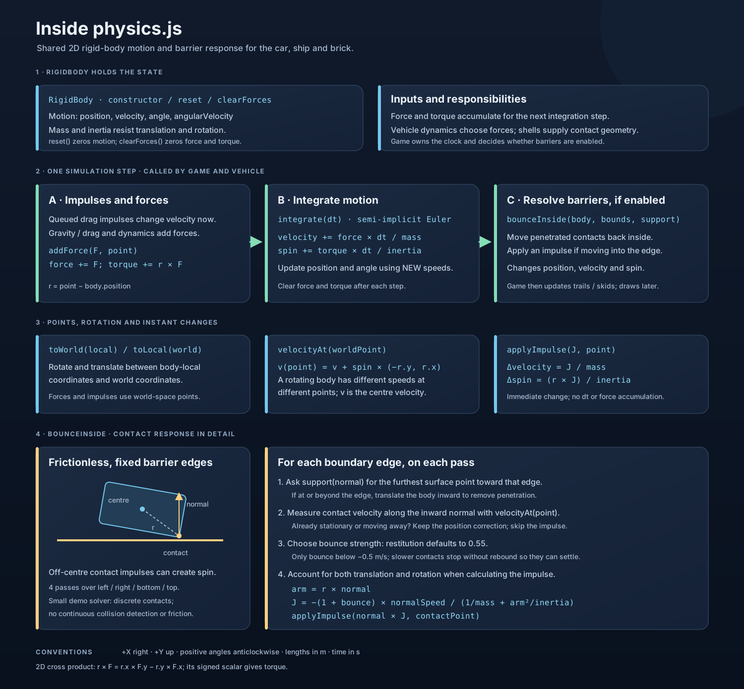
The rigid body tracks position and velocity alongside angle and angular velocity. A force through its centre changes its motion; a force applied away from the centre can also turn it. The simulation adds up the forces and torque, updates velocity, then advances position and angle. A point on a rotating body has its own velocity, combining the body's movement with the motion around its centre.
Barriers use that same point velocity. When a shape crosses an edge, the simulation moves it back inside and applies a contact impulse if it is moving into the barrier. An off-centre impact can therefore change both its velocity and its spin. This is a simple barrier solver, with frictionless edges, rather than a general collision system.
The deliberately approximate tyres
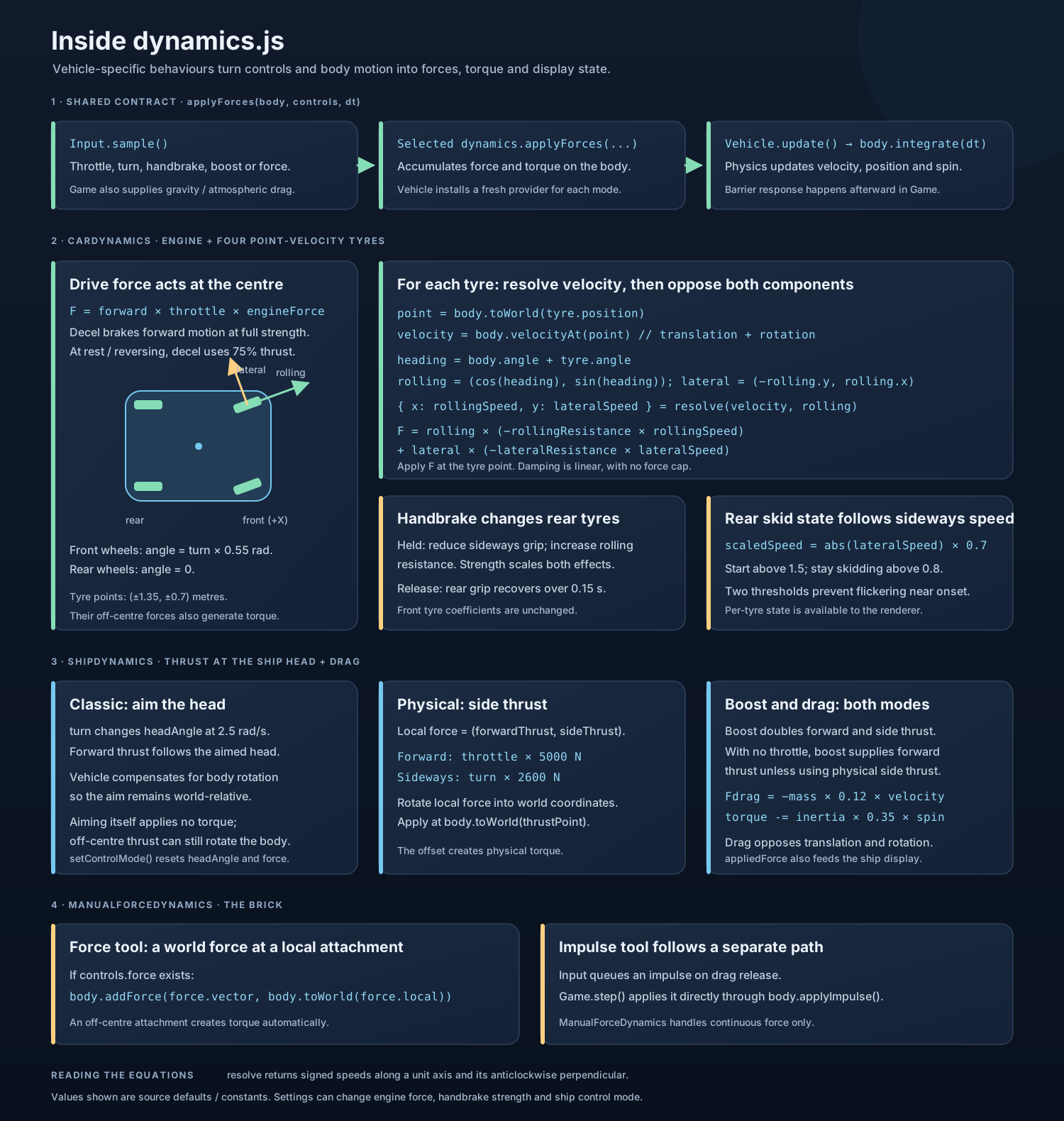
For each tyre, the Car measures the velocity at its position and resolves it into two components: along the wheel's heading and sideways across it. It applies a small resistance to rolling and a much stronger resistance to sideways motion. Steering changes the front wheels' headings, so their forces also turn the body. The handbrake increases rear rolling resistance and reduces rear sideways grip.
Those resistance forces are proportional to velocity, without a force cap. That is a convenient damping model rather than a realistic account of tyre friction, slip or available grip. It produces the useful feeling of wheels resisting sideways movement with very little machinery. The Ship and Brick use the same physics core with different ways of applying forces.
Putting the pieces together
The Vehicle coordinator asks the selected dynamics object to apply its forces, then advances the rigid body. It also converts the shell's local points into world positions for drawing and finds the surface point facing each barrier. When a flat face touches a barrier, it uses the midpoint of the contacting points, avoiding the artificial spin that choosing a single corner would introduce.